Laptop & Tablet Parts
 Desktop & All-in-one Parts
 Dell Server Parts


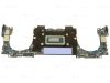
In this Dell laptop tutorial we are going to show you how to install and replace the Motherboard on your XPS 13 Plus 9320 laptop. These installation instructions have been made into 18 easy to follow printable steps. We have also created a video tutorial that shows you how to install your XPS 13 Plus 9320 Motherboard.
Before you begin
 Please take the time read the following safety guidelines when working on static sensitive electrical components.
Dell repair manual service precautions
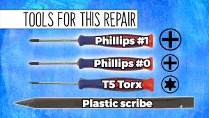
Tools needed for this laptop repair
- 1 x Phillips #1 screwdriver
- 1 x Phillips #0 screwdriver
- 1 x T5 Torx screwdriver
- 1 x small plastic scribe
XPS Plus 9320 Motherboard
XPS 13 Plus 9320 Motherboard
|
Eligible for FREE Economy Shipping. Only 1 left in stock - order soon. 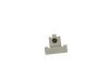
Eligible for $5.00 1st Class Shipping. Only 1 left in stock - order soon. 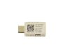
Eligible for $5.00 1st Class Shipping. In Stock DIY Discount - Parts-People.com offers 5% off to all DO-IT-YOURSELFERS!
Use this coupon code to save 5% off these parts DIYM514
|
Video tutorial repair manual
Installation and Removal Instructions
XPS 13 Plus 9320 Motherboard
Step 1
- Before you begin: If you need help at any point, you can always contact Parts-People Motherboard Repair Department for help with your diagnosis or repair.
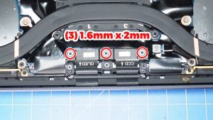
Step 5
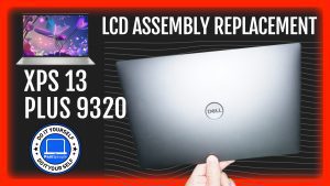
- Unscrew and remove the bracket and disconnect the display cable (3 x 1.6mm x 2mm) (3 x M1.6 x 2.5mm).
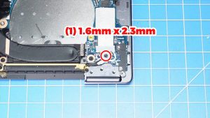
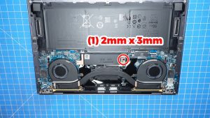
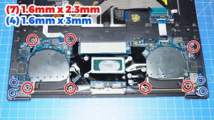
Step 6
- Unscrew and remove the bracket (1 x 1.6mm x 2.3mm).
- Disconnect the WiFi antenna cables.
Step 7
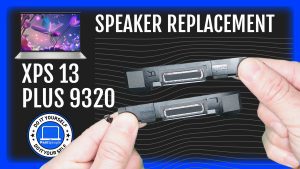
- Disconnect the speaker cables.
Step 8
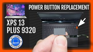
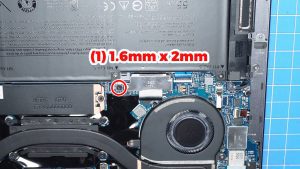
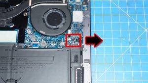
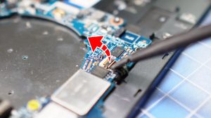
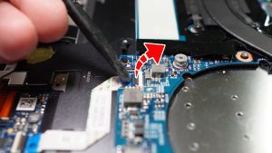
- Unclip the locking tab and disconnect the power button cable.
Step 9
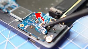
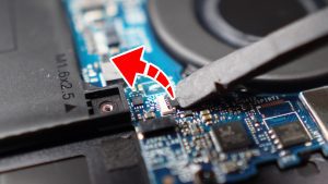
- Unclip the locking tab and disconnect the capacitive touchpanel cable.
Step 10
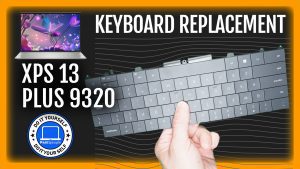
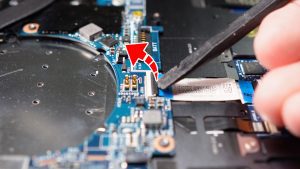
- Unclip the locking tab and disconnect the keyboard controller cable.
Step 11
- Unclip the locking tab and disconnect the haptic module cable.
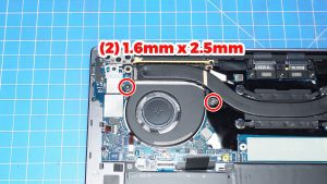
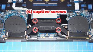
Step 13
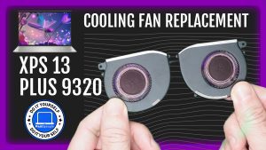
- Unclip the locking tabs to disconnect the cooling fan cables.
Step 17
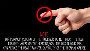
- NOTE: For maximum cooling of the processor, do not touch the heat transfer areas on the heatsink/CPU. The oils in your skin can reduce the heat transfer capability of the thermal grease.
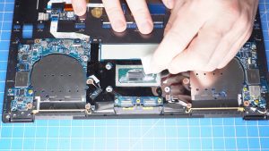
Step 18
- NOTE: Before replacing your heatsink it's important to wipe away any old thermal paste from the heatsink and CPU.
- Then apply a small amount of new thermal paste to the CPU before reinstalling your heatsink.
- ***FOLLOW THE ORIGINAL STEPS IN REVERSE TO REASSEMBLE YOUR LAPTOP.
XPS Plus 9320 Motherboard
XPS 13 Plus 9320 Motherboard
|
|
Eligible for FREE Economy Shipping. Only 1 left in stock - order soon.
Eligible for $5.00 1st Class Shipping. Only 1 left in stock - order soon.
Eligible for $5.00 1st Class Shipping. In Stock DIY Discount - Parts-People.com offers 5% off to all DO-IT-YOURSELFERS!
Use this coupon code to save 5% off these parts DIYM514
|