Laptop & Tablet Parts
 Desktop & All-in-one Parts
 Dell Server Parts


In this Dell laptop tutorial we are going to show you how to install and replace the Palmrest Keyboard Assembly on your XPS 13 (9315) laptop. These installation instructions have been made into 25 easy to follow printable steps. We have also created a video tutorial that shows you how to install your XPS 13 (9315) Palmrest Keyboard Assembly.
Before you begin
 Please take the time read the following safety guidelines when working on static sensitive electrical components.
Dell repair manual service precautions
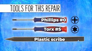
Tools needed for this laptop repair
- 1 x Torx #5 screwdriver
- 1 x Phillips #0 screwdriver
- 1 x small plastic scribe
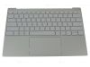
XPS 9315 Palmrest Keyboard Assembly
XPS 13 9315 Palmrest Keyboard Assembly
|
Eligible for $5.00 Economy Shipping. In Stock 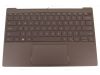
Eligible for $5.00 Economy Shipping. Only 4 left in stock - order soon. 
Eligible for $5.00 1st Class Shipping. In Stock DIY Discount - Parts-People.com offers 5% off to all DO-IT-YOURSELFERS!
Use this coupon code to save 5% off these parts DIYM514
|
Video tutorial repair manual
Installation and Removal Instructions
XPS 13 (9315) Palmrest Keyboard Assembly

Step 1
- Before you begin: If you need help at any point, you can always contact Parts-People Repair Department for help with your diagnosis or repair.
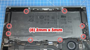
Step 3
- Disconnect the battery cable.
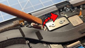
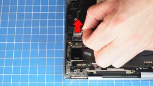
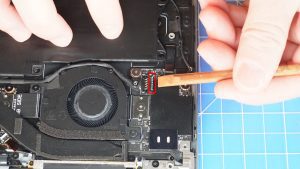
Step 5
- Unsnap the locking tab and disconnect the cooling fan cable.
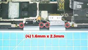
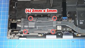
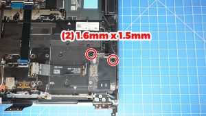
Step 8
- Unscrew the 2 LCD cable brackets (4 x 1.6mm x 2.3mm).
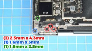
Step 9
- Unscrew and lift the left LCD hinge (3 x 2.5mm x 4.3mm) (1 x 1.6mm x 3mm) (1 x M1.6 x 2.5mm).
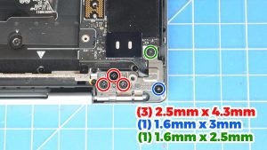
Step 10
- Unscrew and lift the right LCD hinge (3 x 2.5mm x 4.3mm) (1 x 1.6mm x 3mm) (1 x M1.6 x 2.5mm).
Step 12
- Unsnap the locking tab and then disconnect the touchpad cable.
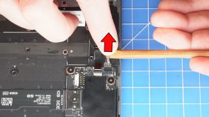
Step 13
- Disconnect the I/O board cable from the motherboard lifting from the outside of the connector.
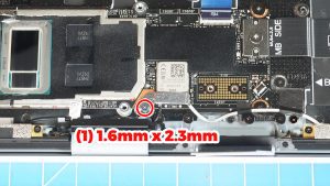
Step 15
- Unscrew and remove the WiFi bracket (1 x 1.6mm x 2.3mm).
- Disconnect the WiFi antenna cables.
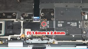
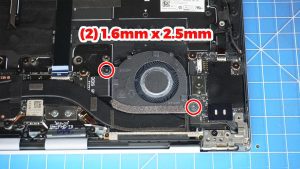
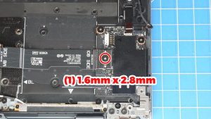
Step 16
- Unscrew and then disconnect the I/O circuit board (1 x 1.6mm x 2.8mm).
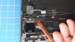
Step 18
- Disconnect the I/O board cable lifting from the outside of the connector as shown.
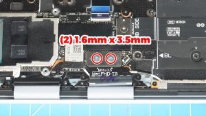
Step 19
- Unscrew and disconnect the I/O circuit board cable.
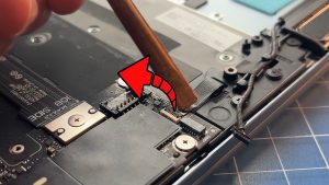
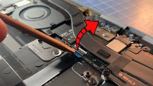
Step 20
- Unsnap the locking tab and disconnect the power button cable.

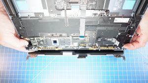
Step 23
- The remaining piece is the Palmrest Keyboard Assembly.
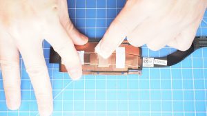
Step 24
- BEFORE REINSTALLING YOUR HEATSINK: Wipe away any old thermal paste from the CPU and heatsink. You can use a clean, dry paper towel. Avoid making contact with your fingers as the oil from your skin can reduce the heat transfer capability of the thermal paste.
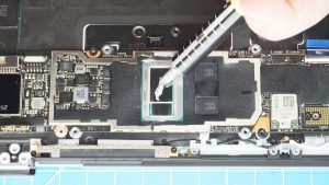
Step 25
- Then apply a small amount of thermal paste to the CPU chips.
- You can optionally spread the thermal paste evenly across the CPU using a clean, flat surface.
- ***FOLLOW THE ORIGINAL STEPS IN REVERSE TO REASSEMBLE YOUR LAPTOP.
XPS 9315 Palmrest Keyboard Assembly
XPS 13 9315 Palmrest Keyboard Assembly
|
|
Eligible for $5.00 Economy Shipping. In Stock
Eligible for $5.00 Economy Shipping. Only 4 left in stock - order soon.
Eligible for $5.00 1st Class Shipping. In Stock DIY Discount - Parts-People.com offers 5% off to all DO-IT-YOURSELFERS!
Use this coupon code to save 5% off these parts DIYM514
|