Laptop & Tablet Parts
 Desktop & All-in-one Parts
 Dell Server Parts


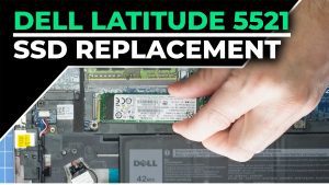
In this Dell laptop tutorial we are going to show you how to install and replace the LCD Back Cover on your Latitude 5521 laptop. These installation instructions have been made into 12 easy to follow printable steps. We have also created a video tutorial that shows you how to install your Latitude 5521 LCD Back Cover.
Before you begin
 Please take the time read the following safety guidelines when working on static sensitive electrical components.
Dell repair manual service precautions
Tools needed for this laptop repair
- 1 x Phillips #0 screwdriver
- 1 x small plastic scribe
Latitude 5521 LCD Back Cover
Latitude 5521 LCD Back Cover
|
$59.95
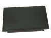
Dell Inspiron 15z 5523 3521 5521 1570 / Studio 1569 15.6" WXGAHD LCD LED Widescreen - Matte - RDMMH Eligible for FREE Economy Shipping. In Stock 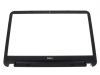
Eligible for $5.00 Economy Shipping. In Stock 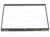
Eligible for $5.00 Economy Shipping. In Stock DIY Discount - Parts-People.com offers 5% off to all DO-IT-YOURSELFERS!
Use this coupon code to save 5% off these parts DIYM514
|
Video tutorial repair manual
Installation and Removal Instructions
Latitude 5521 LCD Back Cover

Step 1
- Before you begin: If you need help at any point, you can always contact Parts-People Repair Department for help with your diagnosis or repair.

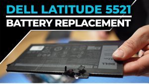
Step 2
- Use a Phillips Screwdriver to unscrew the Bottom Base (9 x captive screws).
- Use a Plastic Scribe to pry apart and remove the Bottom Base Cover.
Step 4
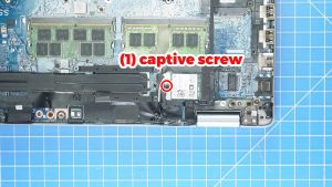
- Unscrew and remove the Wifi bracket (1 x captive screw).
- Disconnect the antenna cables.
- Slide out the WiFi Card.
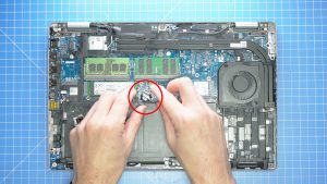
Step 5
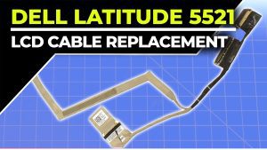
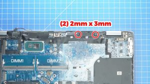
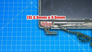
- Unscrew and remove the LCD cable bracket.
- Pull out the 1st LCD cable connector.
- Unsnap the locking clip and pull out the 2nd LCD cable connector.
- Pull out the 3rd LCD cable connector.
Step 6
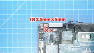
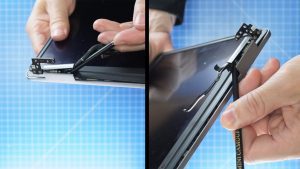
- Unscrew the hinges and then open up the LCD assembly (6 x M2.5 x 5mm).
- Separate the LCD assembly from the Palmrest.
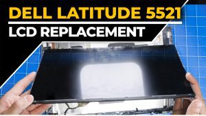
Step 7
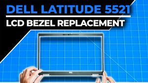
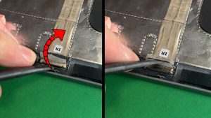
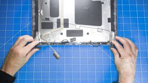
- Insert a plastic scribe into the hinge cover openings and separate the LCD Bezel from the LCD Back Cover.
- Carefully work your way around unsnapping it until it's fully detached.
Step 9
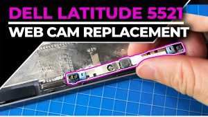
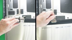
- Peel away the tape covering the LCD connector on the back of the screen.
- Unsnap the locking clip and disconnect the LCD Cable.
Step 11
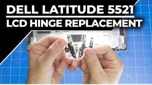
- Remove the LCD hinges.
Step 12
- The remaining piece is the LCD Back Cover.
Latitude 5521 LCD Back Cover
Latitude 5521 LCD Back Cover
|
|
$59.95
Dell Inspiron 15z 5523 3521 5521 1570 / Studio 1569 15.6" WXGAHD LCD LED Widescreen - Matte - RDMMH Eligible for FREE Economy Shipping. In Stock
Eligible for $5.00 Economy Shipping. In Stock
Eligible for $5.00 Economy Shipping. In Stock DIY Discount - Parts-People.com offers 5% off to all DO-IT-YOURSELFERS!
Use this coupon code to save 5% off these parts DIYM514
|