Laptop & Tablet Parts
 Desktop & All-in-one Parts
 Dell Server Parts


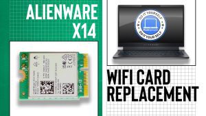
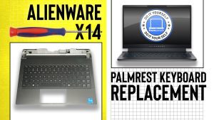
In this Dell laptop tutorial we are going to show you how to install and replace the Palmrest Keyboard Assembly on your Alienware x14 laptop. These installation instructions have been made into 26 easy to follow printable steps. We have also created a video tutorial that shows you how to install your Alienware x14 Palmrest Keyboard Assembly.
Before you begin
 Please take the time read the following safety guidelines when working on static sensitive electrical components.
Dell repair manual service precautions
Tools needed for this laptop repair
- 1 x Phillips #0 screwdriver
- 1 x small plastic scribe
Alienware x14 Palmrest Keyboard Assembly
Alienware x14 Palmrest Keyboard Assembly
|
Eligible for $5.00 1st Class Shipping. Only 1 left in stock - order soon. 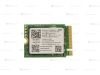
Eligible for $5.00 1st Class Shipping. Only 1 left in stock - order soon. 
Eligible for $5.00 1st Class Shipping. Only 1 left in stock - order soon. DIY Discount - Parts-People.com offers 5% off to all DO-IT-YOURSELFERS!
Use this coupon code to save 5% off these parts DIYM514
|
Video tutorial repair manual
Installation and Removal Instructions
Alienware x14 Palmrest Keyboard Assembly

Step 1
- Before you begin: If you need help at any point, you can always contact Parts-People Repair Department for help with your diagnosis or repair.

Step 3
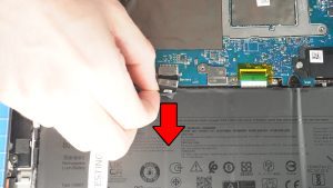
- Disconnect the battery cable.
Step 4
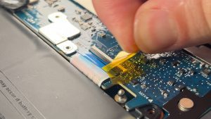
- Unclip the locking tab and disconnect the keyboard controller cable.
Step 6
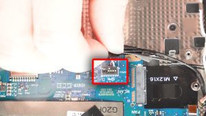
- Disconnect the speaker cable.
Step 8
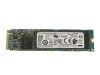
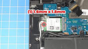
- Unscrew and remove the WiFi bracket (1 x 1.6mm x 1.8mm).
- Disconnect the antenna cables.
- Slide out the WiFi Card.
Step 9
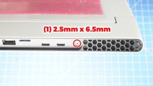
- Unscrew and slide off the Rear I/O Cover (2 x 2.5mm x 6.5mm).
Step 10
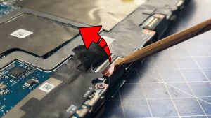
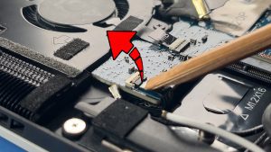
- Peel back the adhesive tape to expose the I/O board cable.
- Unclip the locking tab and disconnect the I/O board cable.
Step 11
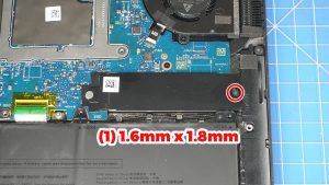
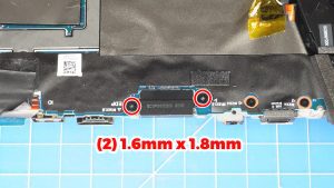
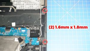
- Unscrew and remove the LCD cable bracket (2 x 1.6mm x 1.8mm).
- Disconnect the LCD cable.
Step 12
- Unsnap the locking tab and then disconnect the power button cable.
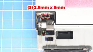
Step 14
- Unscrew and slide off the LCD cable bracket )1 x 1.6mm x 1.8mm).
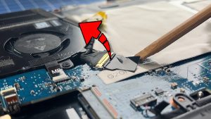
Step 16
- Unsnap the locking tab and disconnect the headset port cable.
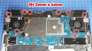
Step 17
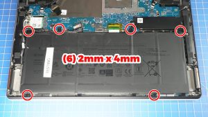
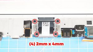
- Unscrew and remove the Motherboard (9 x M2 x 4mm).
- Make sure to carefully route the headset port cable between the cooling fan and the motherboard during the removal.
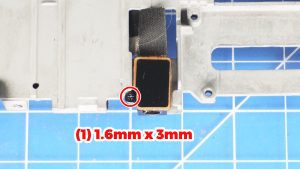
Step 19
- Unscrew and remove the Headset Port (1 x 1.6mm x 3mm).
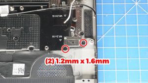
Step 20
- Unscrew and remove the Power Button (2 x 1.2mm x 1.6mm).
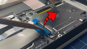
Step 21
- Unclip the locking tabs and disconnect the keyboard controller board cables.
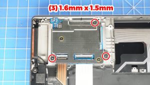
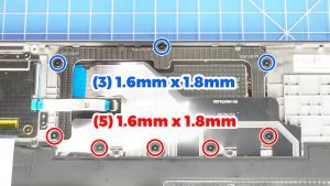
Step 22
- Unscrew and remove the keyboard controller bracket (3 x 1.6mm x 1.5mm).
Step 23
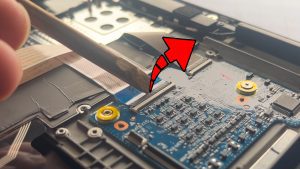
- Unclip the locking tabs and disconnect the keyboard controller board cables.
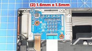
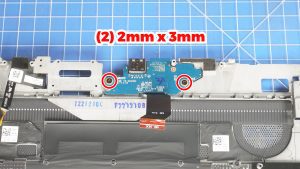
Step 24
- Unscrew and remove the keyboard controller board (2 x 1.6mm x 1.5mm).
Step 26
- The remaining piece is the Palmrest Keyboard Assembly.
- ***FOLLOW THE ORIGINAL STEPS IN REVERSE TO REASSEMBLE YOUR LAPTOP.
Alienware x14 Palmrest Keyboard Assembly
Alienware x14 Palmrest Keyboard Assembly
|
|
Eligible for $5.00 1st Class Shipping. Only 1 left in stock - order soon.
Eligible for $5.00 1st Class Shipping. Only 1 left in stock - order soon.
Eligible for $5.00 1st Class Shipping. Only 1 left in stock - order soon. DIY Discount - Parts-People.com offers 5% off to all DO-IT-YOURSELFERS!
Use this coupon code to save 5% off these parts DIYM514
|