Laptop & Tablet Parts
 Desktop & All-in-one Parts
 Dell Server Parts


In this Dell laptop tutorial we are going to show you how to install and replace the Palmrest Keyboard Assembly on your Alienware x15 R1 laptop. These installation instructions have been made into 32 easy to follow printable steps. We have also created a video tutorial that shows you how to install your Alienware x15 R1 Palmrest Keyboard Assembly.
Before you begin
 Please take the time read the following safety guidelines when working on static sensitive electrical components.
Dell repair manual service precautions
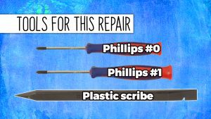
Tools needed for this laptop repair
- 1 x Phillips #0 screwdriver
- 1 x Phillips #1 screwdriver
- 1 x small plastic scribe
Alienware x15 R1 Palmrest Keyboard Assem
Alienware x15 R1 Palmrest Keyboard Assembly
|
Eligible for FREE Economy Shipping. In Stock 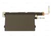
Eligible for $5.00 1st Class Shipping. In Stock 
Eligible for $5.00 1st Class Shipping. Only 19 left in stock - order soon. DIY Discount - Parts-People.com offers 5% off to all DO-IT-YOURSELFERS!
Use this coupon code to save 5% off these parts DIYM514
|
Video tutorial repair manual
Installation and Removal Instructions
Alienware x15 R1 Palmrest Keyboard Assembly

Step 1
- Before you begin: If you need help at any point, you can always contact Parts-People Repair Department for help with your diagnosis or repair.
Step 2
- Use a Phillips Screwdriver to loosen the Bottom Base Cover screws (4 x M2.5 x 7mm) (2 x captive screws).
- Use a Plastic Scribe to pry apart and remove the Bottom Base Cover.
Step 3
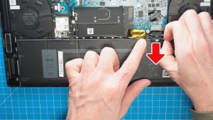
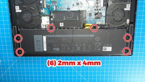
- To protect your laptop from static discharge, disconnect the Battery.
Step 5
Step 6
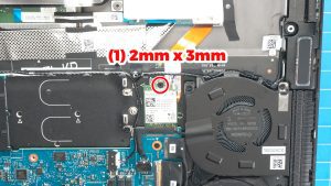
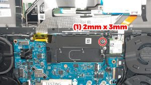
- Unscrew and slide out the SSD bracket (1 x M2 x 3mm).
- Separate the M.2 NVMe SSD from the bracket.
Step 8
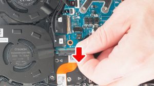
- Disconnect the left and right cooling fans.
Step 9
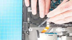
- Remove the speaker cable and antenna cable from the routing guides on the left cooling fan.
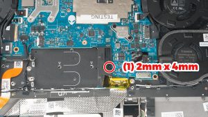
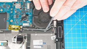
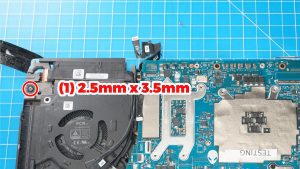
- Unscrew and remove the Left Cooling Fan (3 x M2 x 4mm).
Step 10
- Remove the speaker cable and the antenna cable from the routing guides on the right cooling fan.
- Unscrew and remove the Right Cooling Fan (3 x M2 x 4mm).
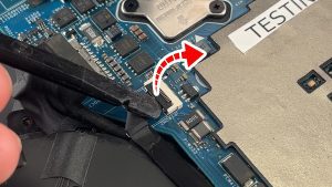
Step 11
- Unclip the locking tab to release the left rear I/O cover cable.
- Disconnect the rear I/O cover cable.
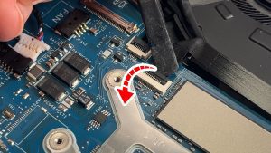
Step 12
- Unclip the locking tab to release the right rear I/O cover cable.
- Disconnect the rear I/O cover cable.
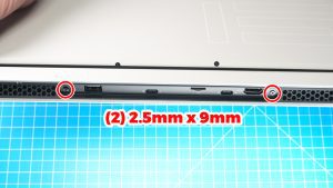
Step 13
- Unscrew and slide off the rear I/O cover (2 x 2.5mm x 9mm).
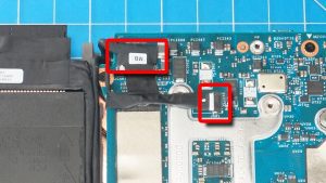
Step 14
- Disconnect the left LCD cables.
Step 15
- Peel off the protective tape.
- Unclip the locking tab.
- Disconnect the right LCD cable.
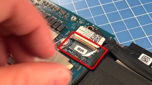
Step 16
- Peel away the tape to expose the the keyboard controller cable connector.
- Unclip the locking tab to disconnect the keyboard controller board.
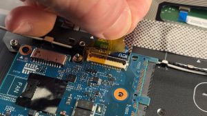
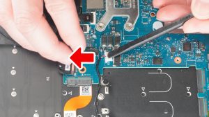
Step 17
- Unclip the locking tab and disconnect the power button cable.
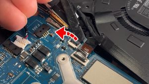
Step 18
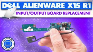
- Unclip the locking tab and disconnect the I/O board cable.
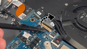
Step 19
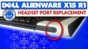
- Disconnect the headset port cable.
- Remove these cables from the routing guide.
- Remove the headset port.
Step 20
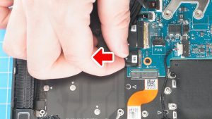
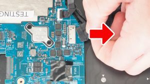
- Disconnect and then unroute the DC jack cable.
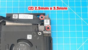
Step 21
- Unscrew and remove the DC jack bracket (2 x 2.5mm x 3.5mm).
- Remove the DC Jack Charging Port.
Step 23
- Disconnect the speaker cable.
- Remove the speakers.
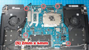
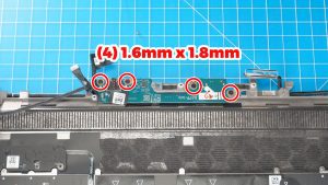
Step 25
- Unscrew and remove the I/O board (4 x 1.6mm x 1.8mm).
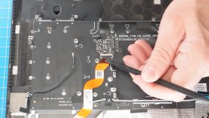
Step 26
- Unclip the locking tab and disconnect the keyboard cable.
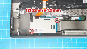
Step 27
- Unscrew and remove the keyboard controller board bracket (2mm x 1.9mm).
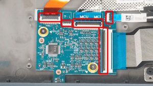
Step 28
- Unclip the locking tabs and disconnect the keyboard controller cables.
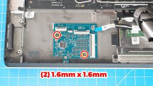
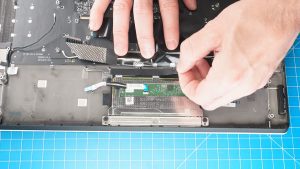
Step 29
- Unscrew and remove the keyboard controller board (2 x 1.6mm x 1.6mm).
Step 30
- Peel away the tape to expose the upper touchpad screws.
- Unscrew and remove the Touchpad (5 x 1.2mm x 1.5mm) (4 x 2mm x 1.9mm).
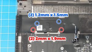
Step 31
- Unscrew and remove the power button (2 x 1.2mm x 1.5mm) (2 x 2mm x 1.9mm).
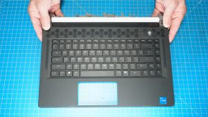
Step 32
- The remaining piece is the Palmrest Keyboard Assembly.
- ***THE REINSTALLATION PROCESS IS AS SIMPLE AS FOLLOWING THESE STEPS IN REVERSE.
Alienware x15 R1 Palmrest Keyboard Assem
Alienware x15 R1 Palmrest Keyboard Assembly
|
|
Eligible for FREE Economy Shipping. In Stock
Eligible for $5.00 1st Class Shipping. In Stock
Eligible for $5.00 1st Class Shipping. Only 19 left in stock - order soon. DIY Discount - Parts-People.com offers 5% off to all DO-IT-YOURSELFERS!
Use this coupon code to save 5% off these parts DIYM514
|