Laptop & Tablet Parts
 Desktop & All-in-one Parts
 Dell Server Parts


In this Dell laptop tutorial we are going to show you how to install and replace the Touchpad Palmrest Keyboard on your XPS 15 (9500) laptop. These installation instructions have been made into 18 easy to follow printable steps. We have also created a video tutorial that shows you how to install your XPS 15 (9500) Touchpad Palmrest Keyboard.
Before you begin
 Please take the time read the following safety guidelines when working on static sensitive electrical components.
Dell repair manual service precautions
Tools needed for this laptop repair
- 1 x T5 Torx screwdriver
- 1 x Phillips #0 screwdriver
- 1 x small plastic scribe
XPS 9500 Touchpad Palmrest Keyboard
XPS 15 9500 Touchpad Palmrest Keyboard
|
$39.95
US Intl - Dell XPS 15 (9500) Touchpad Palmrest Keyboard Assembly - Killer AX1650s - 6JV4G - 08NGH Eligible for $5.00 Economy Shipping. In Stock 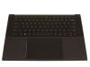
Eligible for $5.00 Economy Shipping. In Stock 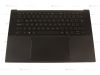
$54.95
SPANISH - Dell XPS 15 (9500) Touchpad Palmrest Keyboard Assembly - Killer AX1650s - M5CT6 - G6RGD Eligible for FREE Economy Shipping. Only 5 left in stock - order soon. DIY Discount - Parts-People.com offers 5% off to all DO-IT-YOURSELFERS!
Use this coupon code to save 5% off these parts DIYM514
|
Video tutorial repair manual
Installation and Removal Instructions
XPS 15 (9500) Touchpad Palmrest Keyboard

Step 1
- Before you begin: If you need help at any point, you can always contact Parts-People Repair Department for help with your diagnosis or repair.

Step 2
- Use a Torx Screwdriver to unscrew the Bottom Base Cover (8 x M2 x 3mm Torx).
- ***THE REMAINING SCREWS AFTER THIS STEP WILL REQUIRE A PHILLIPS SCREWDRIVER.
- Use a Plastic Scribe to pry apart and remove the Bottom Base Cover.
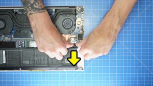
Step 3
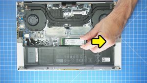
- Disconnect the Battery.
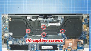
Step 11
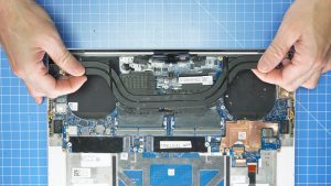
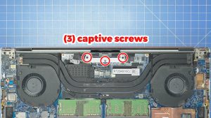
- Unscrew and remove the Heatsink (4 X captive screws).
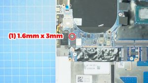
Step 12
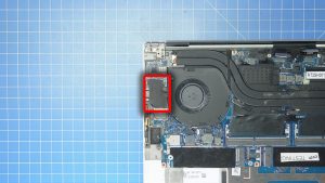
- Unscrew and remove the WiFi bracket (1 X 1.6mm x 3mm).
- Disconnect the antenna cables.
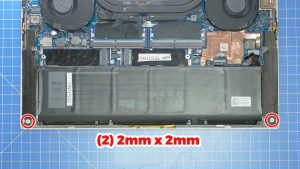
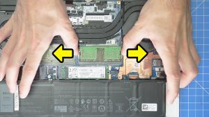
Step 13
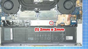
Step 14
- Unscrew and remove the LCD cable bracket (3 X captive screws).
- Disconnect and LCD cables.
- Unscrew and disconnect the LCD cable holder (2 X 1.6mm x 3mm).
Step 16
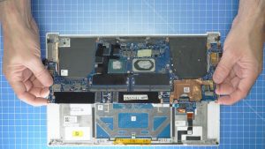
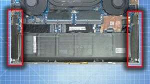
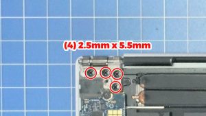
- Unscrew the left and right LCD hinges (8 X 2.5mm x 5.5mm).
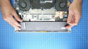
- Separate the palmrest from the LCD Screen Assembly.
Step 17
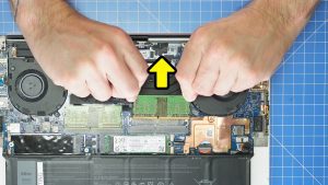
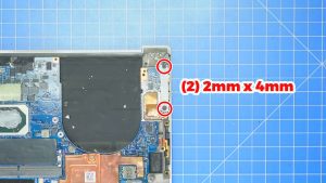
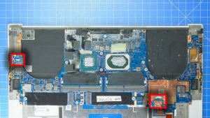
- Unclip the locking tabs then disconnect the motherboard cables.
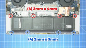
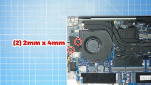
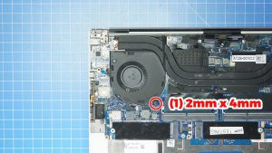
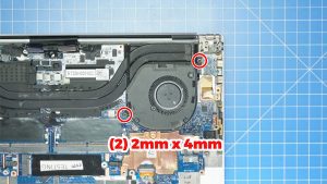
- Unscrew and remove the Motherboard (2 x M2 x 4mm).
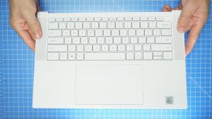
Step 18
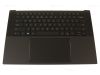
- The remaining piece is the Touchpad Palmrest Keyboard.
- ***FOLLOW THESE STEPS IN REVERSE TO REINSTALL YOUR PART.
XPS 9500 Touchpad Palmrest Keyboard
XPS 15 9500 Touchpad Palmrest Keyboard
|
|
$39.95
US Intl - Dell XPS 15 (9500) Touchpad Palmrest Keyboard Assembly - Killer AX1650s - 6JV4G - 08NGH Eligible for $5.00 Economy Shipping. In Stock
Eligible for $5.00 Economy Shipping. In Stock
$54.95
SPANISH - Dell XPS 15 (9500) Touchpad Palmrest Keyboard Assembly - Killer AX1650s - M5CT6 - G6RGD Eligible for FREE Economy Shipping. Only 5 left in stock - order soon. DIY Discount - Parts-People.com offers 5% off to all DO-IT-YOURSELFERS!
Use this coupon code to save 5% off these parts DIYM514
|