Laptop & Tablet Parts
 Desktop & All-in-one Parts
 Dell Server Parts


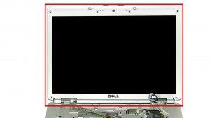
In this Dell laptop tutorial we are going to show you how to install and replace the Cooling Fan on your Vostro 1500 laptop. These installation instructions have be made into 18 easy to follow printable steps. We have also create a video tutorial that shows you how to install your Vostro 1500 Cooling Fan.
Before you begin
 Please take the time read the following safety guidelines when working on static sensitive electrical components.
Dell repair manual service precautions
Tools needed for this laptop repair
- 1 x small phillips head screwdriver
- 1 x small plastic scribe
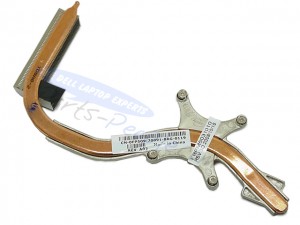
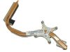
Vostro 1500 Fan
Vostro 1500 Cooling Fan
|
Eligible for $5.00 Economy Shipping. Only 9 left in stock - order soon. 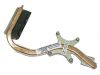
Eligible for $5.00 Economy Shipping. Only 3 left in stock - order soon. 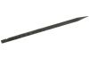
Eligible for $5.00 1st Class Shipping. In Stock DIY Discount - Parts-People.com offers 5% off to all DO-IT-YOURSELFERS!
Use this coupon code to save 5% off these parts DIYM514
|
Video tutorial repair manual
Installation and Removal Instructions
Vostro 1500 Cooling Fan
Step 5
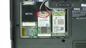
- Unplug the WLAN antenna cables.
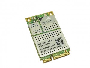
- Unplug the WWAN antenna cables.
Step 7
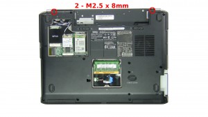
- Remove the bottom hinge screws (2 x M2.5 x 8mm).
- Remove the back hinge screws (2 x M2.5 x 8mm).
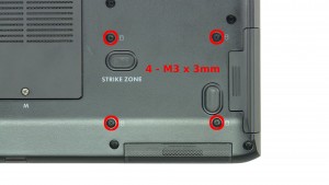
- Remove the bottom base screws (11 x M2.5 x 8mm).
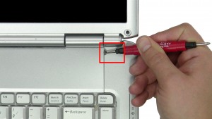
Step 8
- Carefully pry up & unsnap the Power Button Cover, starting on the right and working your way left.
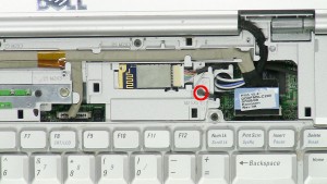
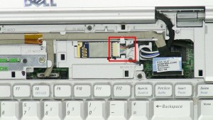
Step 9
- Loosen the LCD cable screw.
- Unplug & loosen the cables.
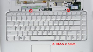
Step 12
- Remove the keyboard screws (2 x M2.5 x 5mm).
- Carefully lift the keyboard to reveal the cable.
- Unplug the cable.
- Remove the Keyboard.
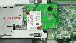
Step 14
- Remove the screws (2 x M2 x 3mm).
- Unplug the cable.
- Unplug & remove the Modem Card from the board.
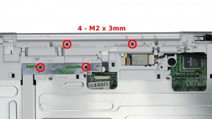
Step 16
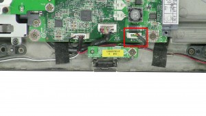
- Unplug the infrared cable.
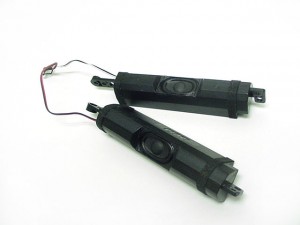
- Unplug the speaker cable.
- Unplug the audio board cable.
Step 17
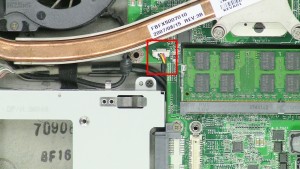
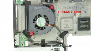
- Unplug the fan cable.
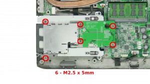
- Remove the motherboard screws (11 x M2.5 x 5mm).
- Remove the Motherboard.
Vostro 1500 Fan
Vostro 1500 Cooling Fan
|
|
Eligible for $5.00 Economy Shipping. Only 9 left in stock - order soon.
Eligible for $5.00 Economy Shipping. Only 3 left in stock - order soon.
Eligible for $5.00 1st Class Shipping. In Stock DIY Discount - Parts-People.com offers 5% off to all DO-IT-YOURSELFERS!
Use this coupon code to save 5% off these parts DIYM514
|